
Maintaining optimal engine performance requires periodic valve adjustments on your 6.7L Cummins. A robust valve cover ensures longevity, and proper torque is essential.
Importance of Regular Valve Adjustment
Consistent valve adjustment is paramount for the 6.7 Cummins engine’s health, directly impacting performance and lifespan. Incorrect valve lash – the gap between valve train components – leads to diminished power, reduced fuel efficiency, and increased wear on critical parts. Too-tight valves can cause burnt valves and cylinder head damage, while excessive lash results in noisy operation and potential valve seat wear.
Regular adjustments, following a detailed 6.7 Cummins valve adjustment sequence PDF, ensure optimal valve timing, maximizing combustion efficiency. This proactive maintenance prevents costly repairs down the line, preserving the engine’s renowned durability and torque output. Ignoring this service can compromise the engine’s ability to handle heavy-duty applications like towing and off-roading, ultimately shortening its operational life.
Overview of the 6.7 Cummins Engine
The 6.7L Cummins turbo diesel engine, a powerhouse in the heavy-duty truck market, is celebrated for its robust construction and exceptional torque capabilities. Introduced in 2007, it quickly gained a reputation for reliability, powering Ram and Dodge trucks, and finding applications in various commercial vehicles. Its design prioritizes durability, enabling it to withstand demanding conditions like towing and off-road use.
Understanding the engine’s architecture is crucial before undertaking maintenance like a 6.7 Cummins valve adjustment sequence PDF guided procedure. The engine features a common-rail fuel injection system, a variable geometry turbocharger, and a sophisticated engine management system. Proper valve adjustment is vital to maintaining the engine’s efficiency and preventing premature wear, ensuring continued performance.
Understanding Valve Train Components
Key components – valves, springs, pushrods, rocker arms, and lifters – work in harmony for efficient combustion. Proper understanding aids adjustment.
Valves (Intake & Exhaust)
The intake valves meticulously control the precise entry of the air-fuel mixture into the combustion chamber, directly influencing engine power and efficiency. Conversely, exhaust valves are equally crucial, responsible for effectively expelling the burnt gases following the combustion process. These valves operate in a synchronized dance, opening and closing at specific times dictated by the camshaft.
In the 6.7L Cummins, both intake and exhaust valves are subject to wear and tear over time, impacting engine performance. Maintaining correct valve clearances is paramount; insufficient clearance can lead to burnt valves, while excessive clearance reduces engine efficiency. Regular inspection and adjustment, as detailed in a 6.7 Cummins valve adjustment sequence PDF, are vital for optimal engine health and longevity.
Valve Springs & Retainers
Valve springs are critical components, responsible for ensuring the valves close completely and promptly after being opened by the camshaft. They counteract the force of the valve train and maintain consistent valve timing. Retainers, working in tandem with valve locks and keepers, securely hold the valves in place, preventing them from lifting too high and potentially colliding with the piston.
The 6.7L Cummins engine utilizes robust valve springs designed to withstand the high stresses of diesel combustion. A 6.7 Cummins valve adjustment sequence PDF will not typically detail spring replacement, but inspecting for cracks or signs of fatigue is recommended during valve adjustments. Proper spring tension and retainer functionality are essential for maintaining accurate valve timing and preventing engine damage.
Pushrods & Rocker Arms
Pushrods act as the mechanical link between the lifters and the rocker arms, transmitting the motion of the camshaft to open and close the valves. They must be straight and free of damage to ensure proper valve operation. Rocker arms pivot on a fulcrum, amplifying the lifter’s movement and transferring it to the valve stem.
In the 6.7L Cummins, these components work under significant stress. A 6.7 Cummins valve adjustment sequence PDF won’t usually cover pushrod or rocker arm replacement unless issues are detected. Inspecting pushrods for bending and rocker arms for wear is crucial during a valve adjustment. Ensuring proper rocker arm geometry is vital for optimal valve lift and engine performance, contributing to the engine’s renowned durability.
Lifters (Hydraulic & Solid) — 6.7 Cummins Specifics

The 6.7L Cummins engine utilizes hydraulic lifters to maintain zero lash, automatically compensating for thermal expansion and valve train wear. These lifters rely on engine oil pressure to function correctly, making clean oil crucial. A 6.7 Cummins valve adjustment sequence PDF will often emphasize checking lifter preload during the adjustment process.
Unlike some engines, the 6.7L Cummins doesn’t typically employ solid lifters; Hydraulic lifters simplify valve adjustment, but require consistent oil pressure. Inspecting for leaks or signs of lifter failure is important. Proper lifter operation is fundamental to the engine’s quiet operation and overall performance, contributing to its reputation for rugged durability and longevity.

Tools Required for Valve Adjustment
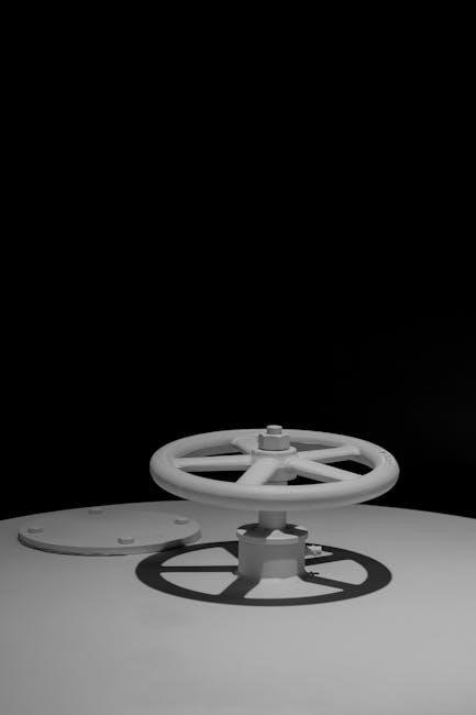
Essential tools include a torque wrench, feeler gauges, socket sets, and wrenches. New valve cover gaskets and sealant are also vital for a successful adjustment.
Torque Wrench
A high-quality torque wrench is absolutely critical for accurately tightening valve cover bolts and rocker arm nuts. The 6.7L Cummins engine demands precise torque specifications to ensure a proper seal and prevent damage to components. Using an inaccurate torque wrench can lead to leaks, valve train noise, or even catastrophic engine failure.
Digital torque wrenches are preferred for their accuracy and ease of use, but a well-maintained click-type torque wrench is also acceptable. Always verify the torque wrench’s calibration before beginning the valve adjustment process. Refer to the Cummins service manual for the specific torque values required for each fastener. Remember to use the correct socket size to avoid rounding off the nuts or bolts.
Feeler Gauges

Precise valve lash adjustment necessitates a quality set of feeler gauges. These tools are used to measure the gap between the rocker arm and the valve stem, ensuring optimal valve operation. The 6.7L Cummins engine requires specific valve lash clearances for both intake and exhaust valves – consulting the service manual is paramount.
A comprehensive set including both inch and metric measurements is recommended. Be sure the feeler gauges are clean and free from burrs, as these can affect accuracy. When checking clearance, apply gentle pressure, and ensure the gauge slides with a slight drag. Incorrect valve lash can lead to reduced engine performance, increased wear, and potential valve damage.

Socket Set & Wrenches
A comprehensive socket set, encompassing both metric and standard sizes, is crucial for disassembling the valve cover and accessing the valve adjustment components. Wrenches, particularly those with offset designs, will aid in reaching adjustment nuts in tight spaces. Deep sockets are often necessary for accessing recessed fasteners.
High-quality tools are essential to prevent rounding off nuts and bolts, which can complicate the process. A ratcheting wrench can significantly speed up the adjustment procedure. Ensure you have the correct size sockets and wrenches to avoid damaging the valve train components. Proper tool selection contributes to a smooth and efficient valve adjustment.
Valve Cover Gaskets & Sealant
New valve cover gaskets are absolutely essential for a leak-free seal upon reassembly. Using old gaskets risks oil leaks and potential engine damage. Opt for high-quality gaskets specifically designed for the 6.7L Cummins engine to ensure a proper fit and reliable performance.
Valve cover sealant, typically RTV silicone, should be applied strategically to critical areas, such as corners and around bolt holes, to further enhance the seal. Avoid excessive sealant, as it can squeeze into the valve train. Proper gasket and sealant application prevents oil contamination and maintains optimal engine operation.

Safety Precautions
Always allow the engine to cool completely before starting. Disconnect the battery’s negative terminal and wear appropriate personal protective equipment during the process.
Engine Cool-Down Procedure
Prior to commencing any valve adjustment work on your 6.7L Cummins, a thorough engine cool-down is absolutely critical. Operating on a hot engine presents significant burn hazards and can also compromise the accuracy of the adjustment process due to thermal expansion. Allow ample time – ideally several hours – for the engine to return to ambient temperature.
Avoid rushing this step; touching hot components like the exhaust manifold or cylinder head can cause severe injuries. A cool engine ensures safe handling of parts and provides a stable platform for precise measurements. Confirm the engine is cool to the touch before proceeding with valve cover removal and subsequent adjustments. Patience here prevents painful consequences!
Battery Disconnection
Before initiating the valve adjustment procedure on your 6.7L Cummins, disconnecting the battery is a non-negotiable safety precaution. This crucial step prevents accidental engine start-up during the process, eliminating the risk of moving parts causing injury. It also safeguards the vehicle’s electrical system from potential shorts or damage during work near electrical components.
Always disconnect the negative terminal first, followed by the positive. This minimizes the chance of sparking. Secure the disconnected cables to prevent accidental contact. Reconnect the battery in reverse order – positive first, then negative – only after the valve adjustment is fully completed and all tools are removed from the engine compartment. Safety first!
Personal Protective Equipment (PPE)
Prioritizing personal safety is paramount when performing a valve adjustment on your 6.7L Cummins engine. Essential PPE includes safety glasses to shield your eyes from debris and potential splashes of fluids. Wear work gloves to protect your hands from sharp edges, hot surfaces, and chemicals like engine oil and sealant;
Consider wearing a long-sleeved shirt and pants to minimize skin exposure. A shop apron can further protect your clothing. If working in a poorly ventilated area, a respirator mask is advisable. Proper footwear, such as closed-toe work boots, is also crucial. Remember, a safe working environment contributes to a successful and trouble-free valve adjustment.

Valve Adjustment Sequence ― Step-by-Step
Follow a precise sequence: remove the valve cover, locate TDC on cylinder one, and meticulously adjust intake and exhaust valves for optimal performance.
Removing the Valve Cover
Begin by disconnecting the negative battery cable to prevent any electrical shorts during the process. Carefully remove any wiring harnesses, sensors, or brackets attached to the valve cover, noting their positions for reassembly. Next, loosen and remove the valve cover bolts in a crisscross pattern to evenly distribute the pressure and avoid warping the cover.
Gently pry the valve cover loose, being mindful of the valve cover gasket which may be stuck. Inspect the gasket for any signs of damage or deterioration; replacement is highly recommended during reassembly. Clean the valve cover and the engine surface thoroughly to ensure a proper seal. A clean workspace is crucial for preventing debris from falling into the engine.
Identifying Top Dead Center (TDC) ― Cylinder #1
Locate the crankshaft pulley and timing marks on the engine block. Rotate the engine clockwise using a socket and breaker bar on the crankshaft bolt until the timing marks align, indicating TDC for cylinder #1. Confirm TDC by removing the glow plug from cylinder #1 and feeling for air pressure escaping as you gently rotate the engine further.
Alternatively, use a piston stop tool to precisely locate TDC. Once confirmed, ensure the timing marks remain aligned throughout the valve adjustment process. Accurate TDC identification is paramount for correct valve timing and optimal engine performance. Double-check your findings before proceeding to the adjustment steps to avoid potential engine damage.
Adjusting Intake Valves
With cylinder #1 at TDC, begin adjusting the intake valves. Loosen the rocker arm nut until you can insert the correct feeler gauge (typically 0.010” ― 0.014”) between the valve stem and the rocker arm. Tighten the nut until a slight drag is felt on the feeler gauge, then tighten an additional quarter turn.
Repeat this process for all intake valves, ensuring the feeler gauge slides with a consistent, slight drag. Avoid over-tightening, as this can lead to valve damage. Proper intake valve adjustment ensures optimal airflow into the cylinders, contributing to efficient combustion and engine power. Re-check each valve after completing the entire set.
Adjusting Exhaust Valves
Following the intake valve adjustment, proceed to the exhaust valves. The exhaust valve clearance is typically smaller than the intake, usually around 0.018” ― 0.022”. Loosen the rocker arm nut for each exhaust valve and insert the appropriate feeler gauge between the valve stem and rocker arm.
Tighten the nut until a slight drag is felt on the feeler gauge, then tighten an additional quarter turn, mirroring the intake valve procedure. Accurate exhaust valve adjustment is crucial for efficient exhaust gas removal, maximizing engine performance and minimizing emissions. Double-check each exhaust valve after completing the entire adjustment sequence.
Repeating the Process for Remaining Cylinders
After successfully adjusting the valves for cylinder #1, rotate the crankshaft one full revolution (360 degrees) clockwise. This brings the next cylinder into its firing position, ready for adjustment. Repeat the entire process – identifying TDC, adjusting intake valves, and then exhaust valves – for each remaining cylinder in the firing order.
Maintain a systematic approach to avoid confusion and ensure no valves are missed. Consistent torque specifications and feeler gauge readings are vital throughout. Thoroughness is key; double-check each valve after completing the adjustment for all cylinders to guarantee optimal engine performance and longevity.

Common Issues & Troubleshooting
Addressing noisy valves, low compression, or valve cover leaks requires careful diagnosis and often stems from improper adjustment or worn components.
Noisy Valves
Persistent ticking or clicking sounds emanating from the valve train often indicate insufficient valve lash. This means there’s excessive clearance between the rocker arm and the valve stem, causing a noticeable tapping noise during engine operation. Incorrect valve adjustment is the primary culprit, but worn lifters or pushrods can also contribute to this issue.
Diagnosing noisy valves involves carefully listening to the engine while it’s running, pinpointing the source of the sound. A mechanic’s stethoscope can be incredibly helpful. If the noise lessens or disappears after a valve adjustment, the problem is likely resolved. However, if the noise persists, further investigation into the valve train components is necessary to identify and replace any worn parts. Ignoring noisy valves can lead to decreased engine performance and potential damage.
Low Compression
Reduced cylinder compression is a serious symptom that can stem from several issues, including improperly seated valves. When valves don’t seal correctly against the valve seats, combustion gases escape during the compression stroke, lowering the overall compression ratio. This results in diminished engine power, reduced fuel efficiency, and increased emissions.
A compression test is crucial for diagnosing low compression. Significant differences in compression between cylinders point towards valve problems, potentially caused by improper adjustment, burnt valves, or carbon buildup on the valve faces. Addressing valve issues promptly is vital to prevent further engine damage; Valve adjustments, valve grinding, or valve replacement may be necessary to restore proper compression and engine performance.
Valve Cover Leaks
Persistent oil leaks around the valve cover are a common issue, often exacerbated by age and thermal cycling. These leaks can originate from deteriorated valve cover gaskets, cracked valve covers, or improperly tightened valve cover bolts. Oil seepage not only creates a mess but can also lead to reduced engine oil levels and potential fire hazards.
When performing a valve adjustment, always replace the valve cover gaskets with new ones and apply a suitable sealant to ensure a proper seal. Torque the valve cover bolts to the manufacturer’s specifications in a crisscross pattern to distribute clamping force evenly. Regularly inspect the valve cover for cracks or damage, and replace it if necessary. Addressing valve cover leaks promptly prevents further complications and maintains engine cleanliness.

Resources & Further Information
Explore online Cummins forums for shared experiences and diagnostic software options. Access official Cummins PDFs for detailed specifications and procedures.
Online Forums & Communities
Engaging with online Cummins communities provides a wealth of practical knowledge and troubleshooting assistance. Forums dedicated to the 6;7L engine are brimming with experienced owners and mechanics who have tackled valve adjustments numerous times. These platforms often host detailed threads, including step-by-step guides, photos, and even videos demonstrating the process.
Searching these forums specifically for “6.7 Cummins valve adjustment sequence” will yield valuable results, often including links to downloadable PDFs and shared experiences regarding common challenges. Don’t hesitate to ask questions – the community is generally very supportive and willing to help. Remember to verify information from multiple sources before implementing any adjustments.
Cummins Official Documentation (PDFs)
Accessing Cummins’ official documentation is crucial for accurate valve adjustment procedures. While not always readily available for free, these PDFs represent the definitive guide for your 6.7L engine. They detail the precise specifications, torque values, and sequences required for a proper adjustment.
Searching the Cummins QuickServe Online portal (often requiring a subscription or account creation) is the primary method for locating these documents. Look specifically for service manuals or technical bulletins related to “valve adjustment” or “valve lash.” These PDFs will provide detailed diagrams and instructions, ensuring you follow the manufacturer’s recommended procedures, minimizing the risk of engine damage.
Diagnostic Tools & Software
While not directly involved in the physical valve adjustment process, diagnostic tools can aid in verifying the results. Post-adjustment, a scan tool can monitor engine performance parameters, identifying any lingering issues potentially related to incorrect valve lash.
Software capable of reading Cummins ECM data can reveal cylinder balance, combustion efficiency, and other metrics. These insights help confirm the adjustment’s effectiveness. Though a PDF sequence guide is essential for the procedure itself, these tools offer a valuable post-adjustment check. Remember, proper adjustment should resolve any pre-existing performance concerns, and diagnostic tools help validate that outcome.